- 2025-01-06 08:46 17010
- 产品价格:面议
- 发货地址:广东深圳福田区 包装说明:不限
- 产品数量:9999.00 个产品规格:不限
- 信息编号:142660305公司编号:8948592
- 刘先生 工程部 经理 微信 13302929585
- 进入店铺 在线留言 QQ咨询 在线询价
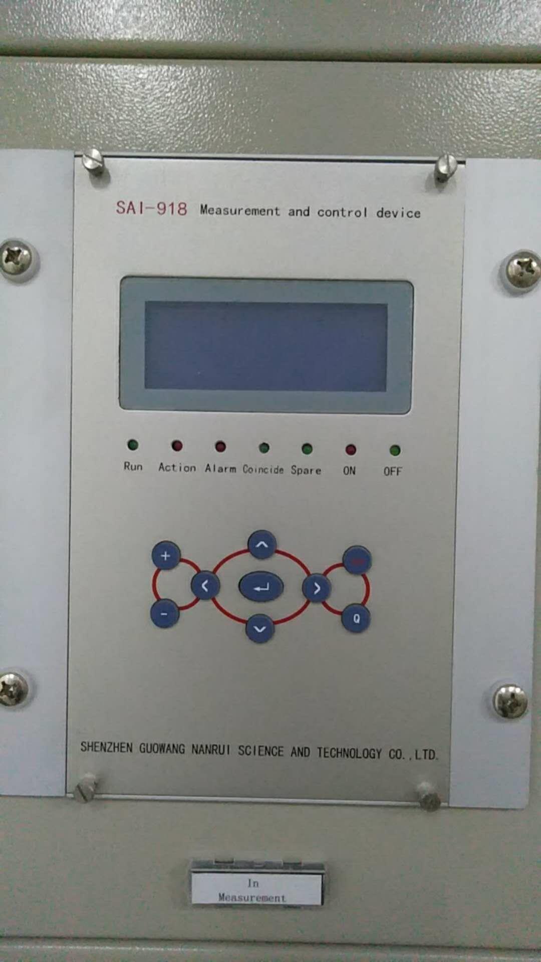
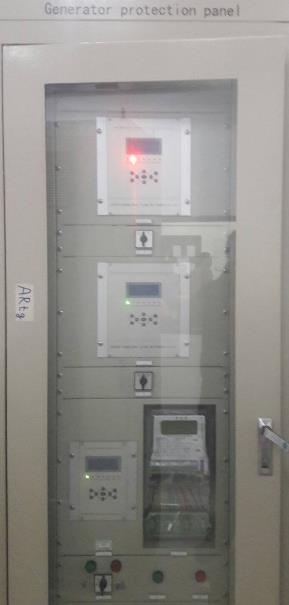
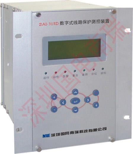
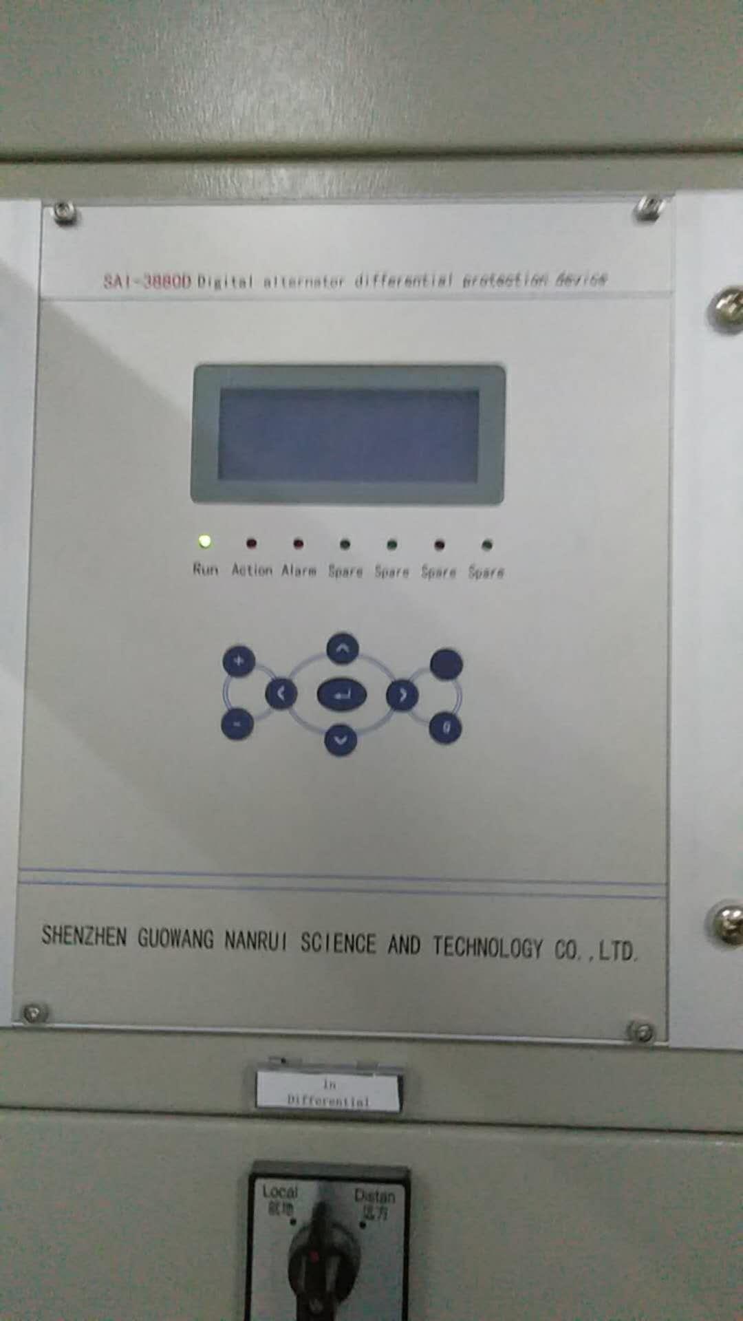
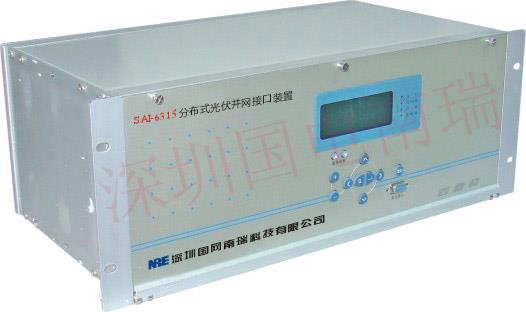
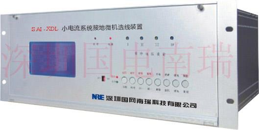
专业订制发电机保护测控装置定制 欢迎来电了解
- 相关产品:
device overview
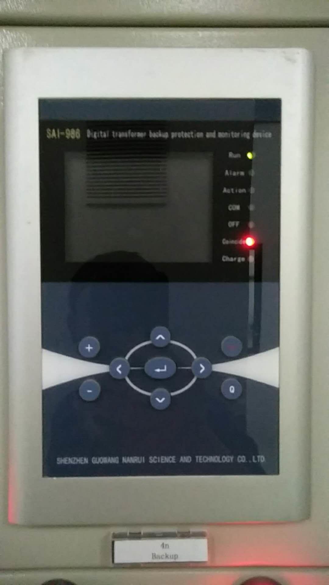
SAI3880D series digital generator protection device with high performance chip supports universal hardware platform, easy to maintain; the Ethernet communication, high-speed data transmission and reliable. Complete localization of Chinese display technology, simple operation.
Based on waterproof, dust, anti vibration design, can be run in a variety of field conditions.
Suitable for capacity of 50MW and below the fire and hydro generator protection.
1.2 main features of the device
An Motorola 32 bit microcontroller technology, the stability and speed of products is guaranteed
The protection. The 14 bit a / D converter, optional measurement module dedicated to the A / D conversion accuracy is up to 24 bits and the measurement indicators easily reach
The purpose of configuration with high capacity RAM and Flash Memory, can record 8 to 50 recorded reports, record the number of events is not less than 1000
An independent tuning of 32 sets of protection setting value, safe and convenient switch
In high precision clock chip, and equipped with GPS hardware circuit for the whole time, system clock synchronization
It is equipped with high speed Ethernet communication interface, and the integration of IEC870-5-103 standard communication protocol
In the electrical design with the machine, no adjustable device
In high grade, quality assurance component selection
An excellent anti-interference performance, panel or installed in the switch cabinet without other anti-jamming module
The purpose of self diagnosis function perfect
The chassis design of waterproof and dustproof and anti vibration.
The purpose of debugging conceptual design
It is proposed that the turning point in the component current Ir0 is set to 1 times the rated current of the high voltage side to ensure that the turn to turn short circuit in the braking current is less than the rated current Ie Ir, there is no braking effect.
Differential current threshold criterion should not be too small, it is recommended to take Icd = (0.3 ~ 0.5) Ie.
The setting of the ratio braking coefficient can be carried out according to the following formula:
Kcd = Kk (Ktx / Fwc + Fph)
Among them, Kk is the reliable coefficient, take 1.3 ~ 1.5
Ktx for the same type coefficient, take 1
Fwc for the current transformer to allow the error, take 0.1
The Fph for the current caused by current transformer unbalanced relative error is 0.05.
Ratio braking coefficient Kcd recommended range of 0.3 to 0.7.Id =∣

2.4 electromagnetic compatibility
2.4.1 electrostatic discharge reactance
Through the GB/T 17626.21998 standard, electrostatic discharge immunity test IV.
2.4.2 radio frequency electromagnetic field radiated immunity
Through the GB/T 17626.31998 standard, RF electromagnetic field immunity test level 3.
2.4.3 electric fast transient pulse group immunity
GB/T 1998 - 17626.4 standard, electrical fast transient pulse group immunity test.
2.4.4 surge (impact) immunity
Through the GB/T 1999 - 17626.5 standard, surge (impact) immunity test 3.
Conduction disturbance degree of 2.4.5 RF field induction
Through the GB/T 17626.61998 standard, RF induction level 3 test conducted
2.4.6 power frequency magnetic field immunity
Through the GB/T 1998 - 17626.8 standard, the power frequency magnetic field immunity 5 level test
2.4.7 pulse magnetic field immunity
Through the GB/T 1998 - 17626.9 standard, the pulse magnetic field immunity 5 level test.
2.4.8 damped oscillatory magnetic field immunity
Through the GB/T 1998 - 17626.10 standard, damped oscillatory magnetic field immunity test 5 levels of test.
2.4.9 oscillation wave immunity
Through the GB/T 1998 - 4 standard, 17626.12 - level oscillation wave immunity test.
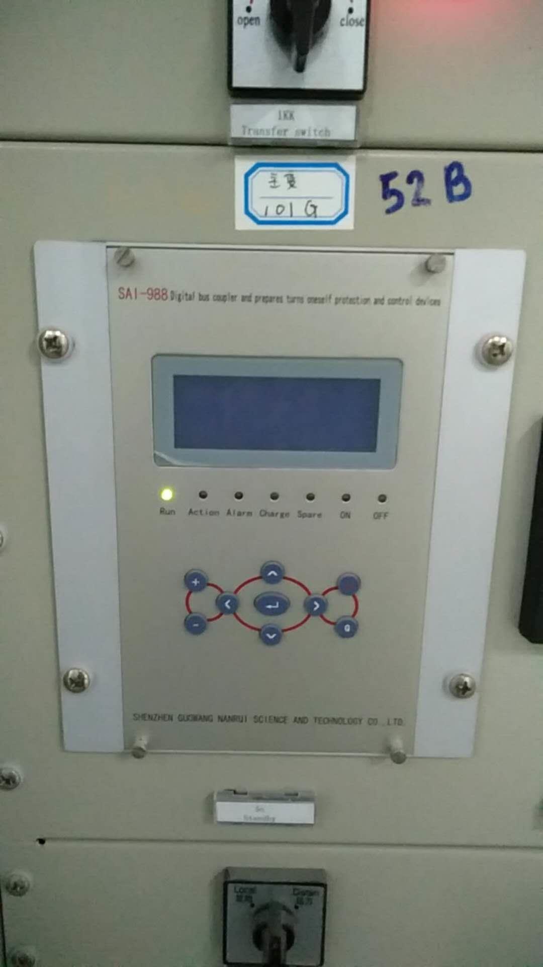
SAI3880D series digital generator protection device with high performance chip supports universal hardware platform, easy to maintain; the Ethernet communication, high-speed data transmission and reliable. Complete localization of Chinese display technology, simple operation.
Based on waterproof, dust, anti vibration design, can be run in a variety of field conditions.
Suitable for capacity of 50MW and below the fire and hydro generator protection.
1.2 main features of the device
An Motorola 32 bit microcontroller technology, the stability and speed of products is guaranteed
The protection. The 14 bit a / D converter, optional measurement module dedicated to the A / D conversion accuracy is up to 24 bits and the measurement indicators easily reach
The purpose of configuration with high capacity RAM and Flash Memory, can record 8 to 50 recorded reports, record the number of events is not less than 1000
An independent tuning of 32 sets of protection setting value, safe and convenient switch
In high precision clock chip, and equipped with GPS hardware circuit for the whole time, system clock synchronization
It is equipped with high speed Ethernet communication interface, and the integration of IEC870-5-103 standard communication protocol
In the electrical design with the machine, no adjustable device
In high grade, quality assurance component selection
An excellent anti-interference performance, panel or installed in the switch cabinet without other anti-jamming module
The purpose of self diagnosis function perfect
The chassis design of waterproof and dustproof and anti vibration.
The purpose of debugging conceptual design

It is proposed that the turning point in the component current Ir0 is set to 1 times the rated current of the high voltage side to ensure that the turn to turn short circuit in the braking current is less than the rated current Ie Ir, there is no braking effect.
Differential current threshold criterion should not be too small, it is recommended to take Icd = (0.3 ~ 0.5) Ie.
The setting of the ratio braking coefficient can be carried out according to the following formula:
Kcd = Kk (Ktx / Fwc + Fph)
Among them, Kk is the reliable coefficient, take 1.3 ~ 1.5
Ktx for the same type coefficient, take 1
Fwc for the current transformer to allow the error, take 0.1
The Fph for the current caused by current transformer unbalanced relative error is 0.05.
Ratio braking coefficient Kcd recommended range of 0.3 to 0.7.Id =∣

2.4 electromagnetic compatibility
2.4.1 electrostatic discharge reactance
Through the GB/T 17626.21998 standard, electrostatic discharge immunity test IV.
2.4.2 radio frequency electromagnetic field radiated immunity
Through the GB/T 17626.31998 standard, RF electromagnetic field immunity test level 3.
2.4.3 electric fast transient pulse group immunity
GB/T 1998 - 17626.4 standard, electrical fast transient pulse group immunity test.
2.4.4 surge (impact) immunity
Through the GB/T 1999 - 17626.5 standard, surge (impact) immunity test 3.
Conduction disturbance degree of 2.4.5 RF field induction
Through the GB/T 17626.61998 standard, RF induction level 3 test conducted
2.4.6 power frequency magnetic field immunity
Through the GB/T 1998 - 17626.8 standard, the power frequency magnetic field immunity 5 level test
2.4.7 pulse magnetic field immunity
Through the GB/T 1998 - 17626.9 standard, the pulse magnetic field immunity 5 level test.
2.4.8 damped oscillatory magnetic field immunity
Through the GB/T 1998 - 17626.10 standard, damped oscillatory magnetic field immunity test 5 levels of test.
2.4.9 oscillation wave immunity
Through the GB/T 1998 - 4 standard, 17626.12 - level oscillation wave immunity test.

